Aidan's Design Study
Part of my honours project is to implement two interfaces for an Intelligent Tutoring System (ITS) for Thermodynamics (tentatively named Thermo-Tutor). The original interface basically aims to make input as efficient as possible, however in an ITS this shouldn't be the primary goal; ITSs are meant to teach something. The experimental interface takes some ideas from the field of cognitive science and sacrifices a certain amount of efficiency for improved learning (hopefully). From an OO design perspective the two interfaces are not drastically different, so I will only be looking at the standard interface. In my haste to get the interface working I invested very little effort in design. I'm sure that upon closer inspection I will find all sorts of stupid decisions.
Thermo-Tutor Interface
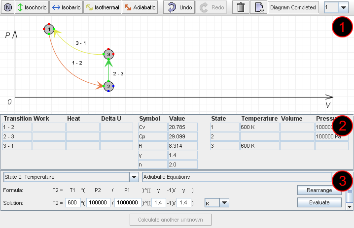
The interface of Thermo-Tutor is primarily a Java applet. The applet has three main components as shown in the following screen shot:
Area 1: Diagram
Here the student is required to draw a diagram of the thermodynamic cycle described in the problem text (not shown). The diagram shows states (as numbered circles) and transitions between those states (labeled according to the states they join). States [1] represent points in the cycle where some properties are known (pressure, volume and/or temperature). Transitions represent the change in the state of the cycle between these states. Each transition is characterised by one property remaining constant throughout that transition. For example the transition 2 - 3 in the diagram is an Isochoric (constant volume) transition.
Area 2: Data Summary
The Data Summary has two purposes. Its main purpose is to store and display all the information that is so far known about the cycle for use in the following step. Its secondary purpose is to allow the student to specify some constants which will also be useful in the following step. The values in the center of the data summary (Cv, Cp etc) are specified explicitly by the student. The other values are entered by the student as they are drawing the diagram. The empty cells in this table are the values which will be calculated in the following step.
Area 3: Formula Workspace
The Formula Workspace is where the student will spend the majority of their time when solving a problem. The previous two steps essentially required the student to deduce some information from the problem statement, no calculations were required. The Formula Workspace allows the student to incrementally calculate the values of properties displayed in the Data Summary. Basically the student is required to complete the Data Summary by calculating each value using some formula. The formulas are predefined in the applet. During this step the student repeatedly iterates through several sub-steps:
- Select the unknown to calculate
- Select the formula to use
- Rearrange the formula to have the correct subject
- Fill in the formula with values from the Data Summary
Each iteration through the steps above will add one more value to the Data Summary, which should hopefully allow subsequent calculations.
Requirements
- Intuitive Interface: In order to facilitate transferable learning it is important that the interface corresponds closely to how students would solve similar problems on paper.
- Maintain Working Solution: The applet must maintain a model of the student's working solution which can be easily manipulated and exported to XML to be sent to the server for checking.
- Maintainability and Extensibility: If Thermo-Tutor is to be extended to support more complex problems in the future, it is likely that the applet will need to be altered and extended also.
Constraints
- I can't change the format required for the XML output. There is a format that Aspire expects to receive, and I must follow this.
Initial Design
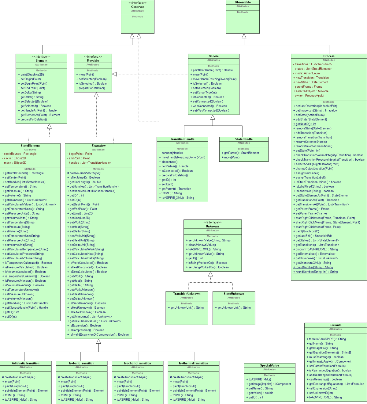
For my design study I will be looking at the design of the model in the applet, as opposed to the view. The following is a UML Class Diagram of the design which occurred very much by accident. Please not that I have left out many details including fields and relationships because the diagram would become too large. These details are described in further detail in the following sections.
Description of Classes
- Process: A thermodynamic cycle
- Element: Something which can be placed on the diagram
- Movable: Something which can be moved on the diagram
- StateElement: A state in the cycle
- Transition: A transition in the cycle
- AdiabaticTransition: Constant energy transition
- IsobaricTransition: Constant pressure transition
- IsochoricTransition: Constant volume transition
- IsothermalTransition: Constant temperature transition
- Handle: Points of components on the diagram which can be joined together
- TransitionHandle: A point on a Transition which can be joined to a StateHandle
- StateHandle: A point on a StateElement which can be joined to a TransitionHandle
- Unknown: A property which is not given in the problem text
- TransitionUnknown: A property of a transition which is not given in the problem text
- StateUnknown: A property of a state which is not given in the problem text
- Formula: A formula which can be used to calculate an unknown
- SpecialValue: A value which can be deduced from the problem text, but is not inherently part of the cycle. These are selected on the DataSummary (see Area 2 above).
Design Critique
To help guide my thinking I considered the design in terms of code smells, riel's heuristics and general design maxims. This is not intended to be a comprehensive analysis of the design, just a starting point. Additional detail about further critique is included in the following sections where it can be more clearly explained and examined.
Beware of many accessors
- There are many unnecessary getters and setters. This is particularly evident in StateElement and Transition.
Avoid god classes / Large class smell
- Process looks like a god class. It takes too much responsibility in managing States and Transitions.
One key abstraction / Single responsibility principle
- Formula really represents two things; a formula and an expression. These things should be separated.
- Both Element and Movable define a method prepareForDeletion(). This is needed for Handle, but still suggests something iffy.
- Elements manage their own properties. Properties are fairly complicated; they have a value, unit, name and can be specified, unknown or calcualted. This should be encapsulated and abstracted out.
- The Unknown class represents a property of a State or Transition which is not given in the problem statement. This value will be calculated in the third step of the problem-solving process. Strangely, Unknown doesn't store a value; that value is still stored on the State or Transition. The problem is that values which are calculated at the end are handled completely differently to values which are specified at the start. This should not be the case. This distinction is necessary, but it should be encapsulated and abstracted so that all values can be handled the same way.
- Handle: isConnected() wasConnected() are neccessary because other classes are involved in connecting and disconnecting Handles. The Handle class should be primarily responsible for connecting and disconnecting itself.
- Process takes too much responsibility in manipulating objects on the diagram. States, Transitions and Handles should be primarily responsible for manipulating themselves as much as possible.
- SpecialValue doesn't contain much behavior. Most of the behavior has leaked out into the view.
Interface should be dependent on model
- Several things handle issues related to the view. These cases may also be violating Separate non-communicating behaviour. Some examples include:
- Process (a class in the model) actually contains a reference to ProcessApplet (a class in the view).
- Element has methods for selection and setting positions.
- The whole Movable interface is a function of the view.
- States and Transitions define their physical properties such as size, position, colour etc.
- Several methods of Handle such as pointIsInHandle() and moveHandleResizingOwner() are functions of the view.
- Process has methods for opening dialog boxes.
- Formulas and SpecialValues store images, and they require a reference to ProcessApplet (a class in the view) to load these images.
Contain contents not parents
- Handles know the State or Transition that they belong to. This could be avoided by using the observer pattern, however I think the gain would be little.
- The relationship between Transitions & States and Unknowns violates this. An Unknown represents a value which is calculated on the State or Transition, but it doesn't actually store this value; it needs to know about its parent to do this.
Move common factors up the hierarchy
- There is a lot of repetition in the concrete Unknown classes. This behaviour could be moved up if Unknown was an abstract class
Beware value switches / Switch statement smell
- The Unknown class makes use of a value switch to determine which property of its respective State or Transition it represents.
- Process.setState(ActionEnum) and Process.setState(Point,int) have a long chain of if statements. This is because these methods have to handle such a wide variety of tasks including adding, moving, deleting and editing States and Transitions.
Avoid no-op overrides / Refused bequest smell
- Implementation of move(Point) in all concrete Transition types is empty. Transitions cannot actually be moved directly after being placed on the diagram. Therefore, Transition should not implement the Movable interface.
Avoid interface bloat
- There are many examples of public methods (and even some fields) that don't need to be public, including:
- Many of the public methods of Process.
- Handle.moveHandleResizingOwner() is only used privately by TransitionHandle.
Hide data within its class
- Both StateElement and Transition have get/set ID. If this were to be done at all (which it shouldn't) it should be done in Element.
- Process.getNextID() is awful. IDs should be passed in at construction time and they should never change.
- Process has some public fields
Methods should use most fields of a class / Temporary field smell
- Unknown defines two methods isBeingWorkedOn() and setBeingWorkedOn(boolean) which may suggest this smell. Better management of data could avoid this.
- Process also has many temporary fields to handle events which occur over some number of calls to it. This can be fixed by moving the functionality elsewhere. In this case this is caused by Process handling many things which belong to the view. It is receiving events from the view which it can't handle easily.
Don't repeat yourself / Duplicate code smell / Shotgun surgery smell
- Much of the code for exporting to XML is duplicated across classes. This should be able to be simplified. Changing the format would probably require changes in many places. However, some small format details are encapsulated in Externaliser.
Long method smell
- Process.setState(ActionEnum) and Process.setState(Point,int) are massive methods. These two methods provide the majority of the functionality of Process. They should be split up so each method has one responsibility. In fact, by reconsidering what Process is actually responsible for this shouldn't even be necessary.
Liskov substitution principle
- Element has begin/end point, yet this doesn't make sense for a StateElement; a State just a position and a fixed size.
- Delta is also defined in Element, yet this is only really a property of a Transition.
Just Silly
- Handle.pointIsInHandle() returns itself, instead of a boolean
- Only StateElement has a setHandles() method, not Transition
- Both StateElement and Transition have getUnknowns() and getCalculatedValues() methods, perhaps this should be in Element?
- All concrete Transitions have a pointIsInElement() that returns itself. Should return boolean, or not exist at all?
Design Improvements
Elements and Properties
Take One
There are currently two types of Elements (States and Transitions) each with three Properties (pressure, temperature and volume for States and delta-U, heat and work for Transitions). In the current design the StateElement and Transition classes fulfill the majority of the role of both Elements and Properties. Separation of concerns suggests these two concepts should be represented by separate classes. TransitionUnknown and StateUnknown represent Properties which were not specified during the first step of problem solving. These are distinguished because they will need to be calculated in the final step of problem solving. However, they are distinguished by separate classes purely so they can be displayed and calculated by the student. It would be better if all Properties were represented in this fashion. The distinction between those specified in step one, and those calculated in step three is unimportant. In step three Elements will easily be able to provide a list of unspecified Properties, which will then be able to be displayed and calculated by the student.
Several factors make Unknown a poor representation of Properties. Note that both StateUnknown and TransitionUnknown contain no fields. This is because all the values of the properties they represent are actually stored in their respective Elements (they are a kind of proxy). As I said previously, they were created purely so they can be displayed an calculated easily by the student. StateUnknown represents pressure, temperature and volume, and TransitionUnknown represents delta-U, heat and work. Again, this is a violation of Separation of concerns. As a result, each contain a Switch statement smell which checks an Enum which defines its type; Beware value switches.
It is sensible to represent Properties separate from the Elements they belong to because a Property is actually fairly complex. A Property has a value, unit and name. It can also be in one of three states; specified, unknown or calculated. We should encapsulate and abstract these distinctions as much as possible.
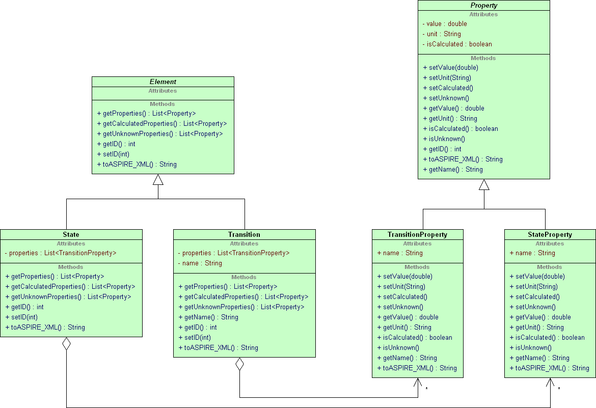
The following diagram shows the portion of the new design concerned with the representation of Elements and Properties:
- All code which belongs to the view has been removed (this will be dealt with in another section)
- Element is now an abstract class as opposed to an interface. Element will be responsible for storing the ID and exporting to XML (at least until I change how things are exported).
- The intelligent children pattern has been used to relate these two parallel hierarchies
- Transition no longer has any subclasses. The distinction between the various types of transitions is irrelevant once code which belongs in the view is removed. This distinction has been replaced by adding the Transition.name property. However, this decision may violate Put semantic constraints in class definition. These subclass will exist in the view because different transitions have different shapes (eg. some are curved) and different constraints (eg. some must be vertical or horizontal).
- TransitionProperty and StateProperty could have subclasses for each of the specific types of property (pressure, temperature, volume etc.), but these would be lazy classes because they would differ only by name. However, this decision also may violate Put semantic constraints in class definition. All an Element's Properties will be created in the constructor of that Element (State or Transition). Adding extra Properties will then be as simple as altering this constructor slightly. This is in keeping with the general philosophy of the open closed principle
- Properties can be in one of three states; unknown, specified or calculated. These distinctions are important for exporting to XML, and also for problem solving procedure. For example, Properties which are specified as unknown in the first step will be calculated by the student in the final step.
Take Two
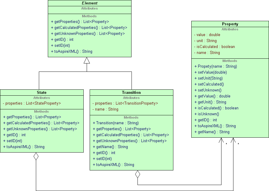
After beginning to code up this solution it occurred to me that the distinction between StateProperties and TransitionProperties is entirely pointless. So the new design is:
Formulas and Equations
Take One
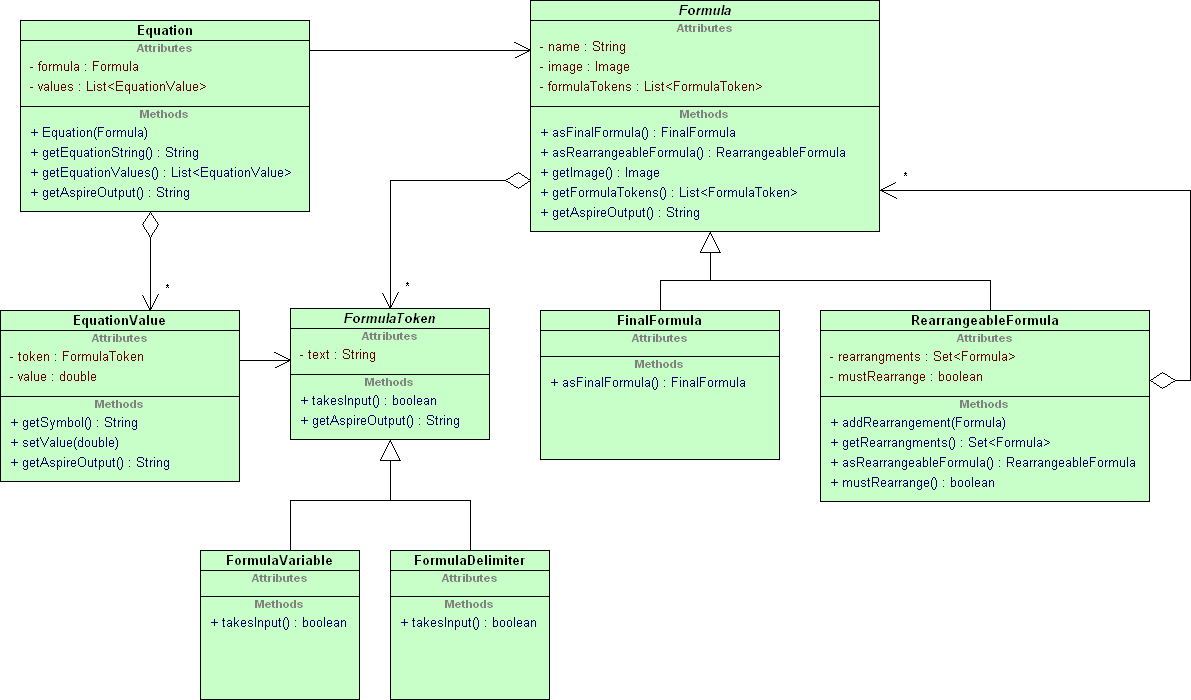
In the current design the Formula class represents both Formulas and Equations. That is it represents both the formula itself, as well as the specific usage of that formula. These two concepts should be represented by separate classes. The design also seems to make excessive use of primitives. Formulas are represented as an array of Strings. Each token in this array either represents a variable or a delimiter. The first token represents a delimiter, the second a variable, and so on in alternating order. This requires the view to interpret the meaning of each token. If this representation were to change, the view would also have to be changed.
The following diagram shows the portion of the new design concerned with the representation of Formulas and Equations:
- Formula: Represents a formula as a list of FormulaTokens. Some FormulaTokens take input (variables), others don't (delimiters). In the view, FormulaTokens which take input will be drawn as textboxes, those that don't will be drawn as labels.
- Formulas are still constructed by passing an array of Strings. Each token in this array still represents a variable or a delimiter in the same fashion as before. But, this String array is not stored in the Formula object, instead it is used to construct a list of FormulaTokens. This part of the design is still quite poor. It would be better to construct a Formula from a String, and parse that String to construct the list of FormulaTokens. However, this parsing procedure would add unnecessary complexity. Parsing could be added later without the need to alter the interface provided by FormulaToken.
- FormulaTokens are constructed for each Formula, although some FormulaTokens will be redundant as they will represent the same variable or delimiter. A Flyweight could be added to make this more efficient, however it is not necessary at this stage.
- Some Formulas can be rearranged (RearrangeableFormula), and some cannot (FinalFormula). This structure resembles Composite, however the intent is quite different. This structure does not represent a hierarchy of whole and part objects. In fact it does not represent a hierarchy at all. It represents how formulas can be rearranged. In general this structure will look like a graph, and can contain cycles (such as when two formulas can be rearranged to one another).
- Formula contains an Image to represent it. It may be argued that this belongs to the view, but a class which only contained an Image and a Formula would be lazy.
- The view will provide an interface to allow the student to firstly select and rearrange the formula they will use. It will then allow the student to fill in the values of the variables in that formula. It will do this by getting the list of FormulaTokens from the Formula. From this it will construct a textbox or a label for each FormulaToken depending on the value returned by takesInput(). When the student fills in the textboxes, the view code will tell the Equation (constructed previously) the value to associate with each FormulaToken. The Equation will then be able to provide a String to represent that equation for exporting to XML. With this design the view only needs to be aware of Formula (and it's subclasses), Equation and FormulaToken.
- Exporting makes use of Recursion introduction. For example, when getting the output from Equation, it gets output from it's EquationValues, collates the results and returns it.
There are some problems with this design that I will attempt to correct, including:
- The "composite like" pattern between Formula, FinalFormula and RearrangeableFormula is not a good solution. This is because it is not being used to model a hierarchy of whole and part objects. FinalFormulas and RearrangeableFormulas are equally valid formulas; it's just that one can be rearranged and the other cannot. In other words, there is no major semantic or behavioral difference between FinalFormula and RearrangeableFormula.
- FormulaToken's subclasses FormulaVariable and FormulaDelimiter exist purely to distinguish the two types of tokens; they do not contain any unique behavior.
- EquationValue represents the variables in an equation and their set value; but there is no class for representing other tokens in the Equation that do not take value.
Take Two
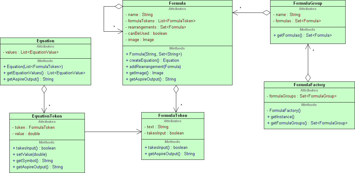
There are several problems in the design above that I attempted to remove with the following design:
The most significant changes I have made are:
- Removed FinalFormula and RearrangeableFormula classes. The Formula class now stores all it's possible rearrangements. If a Formula has no rearrangements then it cannot be rearranged; simple.
- Removed FormulaVariable and FormulaDelimiter classes. The distinction between tokens which take input and those that do not is now represented by the boolean takesInput.
- When we want an Equation object we tell the Formula to create us one, instead of passing the Formula into the Equation constructor. This makes it possible to keep the list of FormulaTokens private to Formula. This is in keeping with hierarchical encapsulation. It also provides a logical place to do some checking of the Formula, and return null if there is some error.
- Equation no longer stores a reference to it's Formula; this wasn't necessary
- Added FormulaGroup class. This represents a logical grouping of formulas. The students will be required to select a formula group before selecting a formula, mostly because there will be so many formulas. A FormulaGroup only contains the "standard" Formulas. There will be other Formulas which are accessible only by rearranging one of the "standard" ones.
- Added FormulaFactory class. This is not an Abstract Factory, it is simply a Singleton which is responsible for creating and assembling all the Formulas so they can be rearranged and putting them into groups. It will make use of lazy initialization for both the Singleton pattern and creating Formulas.
- In the initial design the functionality provided by FormulaGroup and FormulaFactory was provided by several methods in the view which were simply tacked on to an otherwise unrelated class.
In My Defense...
Here I will try to justify why I went for such a simple design (because I know Wal wanted something more sophisticated).
I considered a more sophisticated design which would be able to parse formulas into a parse tree. If we limit ourselves to mathematical expression this task wouldn't be overly difficult. However, I wouldn't actually be making full use of a design like this because the problem I'm trying to solve is actually quite simple. Parsing is not required because I am not performing operations such as checking the formula is valid, or evaluating the equation to get a result. The design only needs to be capable of replacing variables with values and exporting the result.
The current design could be modified to include a parser fairly easily because of the EquationToken class. With a parse tree it is likely that the functionality of this class (primarily setting it's value) would be provided by the nodes of the parse tree. Instead of the client getting all the EquationTokens from the Equation class, it would get all the node tokens (perhaps of some type) from the top of the parse tree. So, the way the client interacts with this design is not overly different to how it would interact with a parse tree design. However, it would still require some pretty substantial re-work.
How It Does What It Should
There are a few things that this part of the system must be able to do well. To help explain the design, I will explain how it does these things.
- Adding new Formulas: It should be fairly easy to add new Formulas to the system. To add new Formulas the developer must simply pass in the full formula as a String and a set of Strings of the variables that exist in that Formula. The Formula handles breaking this string up into a list of FormulaTokens; variables will take input, others will not.
- Allowing Equations to be filled in easily: The view can get an Equation from a Formula very easily by calling Formula.createEquation(). From there the view can display all the EquationTokens as it sees fit, and allow the user to input values for EquationTokens which take input.
- Exporting: It should be easy to export information about Formulas and Equations to XML to be sent to ASPIRE for checking. This design uses Recursion introduction for this purpose. For example, Equation.getAspireOutput() calls the same method on each EquationToken. EquationTokens will output their value if they take input, otherwise they will output their symbol. Exporting Formulas works in a very similar way. The only difference is that it simply always outputs the text of each FormulaToken because they cannot have values.
Separating the Model from the View: States, Transitions and Elements
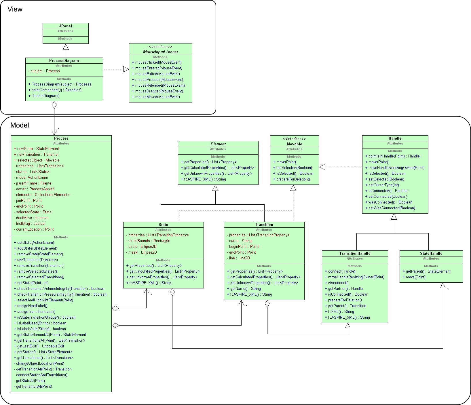
The figure below shows the current design when the alterations made in a previous section (Elements and Properties) are incorporated. There are some details included here that aren't in the main diagram and others that are omitted for clarity. I have also shown the relevant portion of the view because a big part of this design was separating the model and view. This part of the system is perhaps the most fundamental and complex. It is intended to model a thermodynamic cycle (hereafter referred to as a process).
Important points to note:
- A Thermodynamic Process is a cycle of Transitions and States connected by Handles. Each Transition has two TransitionHandles (one at either end) and each State has four StateHandles (one at each clock position 3,6,9 and 12). Handles are only connected to other Handles. A StateHandle can only be connected to a TransitionHandle and vice versa.
- Process class maintains two lists; one of States and another of Transitions.
- It is fairly clear that Process has become a God class. Ideally it should simply be responsible for holding Elements and some general operations on this collection. In reality it is responsible for all the operations associated with adding, removing, joining and disconnecting Elements in the Process. It also stores a large amount of state associated with operations that occur over some amount time as the user interacts with the system. This has resulted in a Temporary field smell. For example, the field Process.pinPoint stores the location of a click so that a subsequent drag can be handled properly.
- Process has some public fields.
To help deconstruct this design I will describe how some common operations are performed:
- Adding a State: Create the State object and pass it to Process.addState(). The State is not actually in the diagram until it is given a position. This occurs when the user clicks on the diagram.
- Removing a State: Pass the State object to Process.removeState(). This also disconnects all the TransitionHandles from each StateHandle on this State. It does this by getting the Transitions that are at the same Point as each StateHandle, and checking each TransitionHandle that belongs to that Transition if it is connected and if so it disconnects it. This is necessary because StateHandles are only aware of what State they belong to, not what TransitionHandle they are connected to. Strangely, TransitionHandles are aware of which Handle they are connected to.
- Adding a Transition: Create the Transition object and pass it to Process.addTransition(). The Transition is not actually in the diagram until it is given a start and end position. This occurs when the user drags between two points on the diagram.
- Removing a Transition: Pass the Transition object to Process.removeTransition(). Removing Transitions is as simple as removing it from the Process.transitions List. We don't need to be concerned about disconnecting any StateHandles that are connected to TransitionHandles which belong to the Transition we are deleting. This is because, as I mentioned before, the StateHandles are not even aware of the TransitionHandles they are connected to.
- Joining States and Transitions: The steps that occur in adding an Element to the diagram are a bit odd. I suspect that Process takes too much responsibility in this process. I will describe this process in terms of how the user creates a diagram with the current interface.
- Click a new state or transition button on the toolbar: This is one of the first five buttons on the toolbar in the interface. This causes Process.setState(ActionEnum) to be called with the appropriate ActionEnum. This method creates the state or transition and stores it in newState or newTransition respectively. This is a possible Temporary field smell.
- Click on the diagram to place the transition or state: This causes Process.setState(Point, int) to be called with the click point and mouse event (click, release or drag). This sets the position of State or Transition which officially places it in the diagram.
- Place a TransitionHandle near a StateHandle so they are joined: This can be done by either drawing the start or end of the Transition near a StateHandle, or by moving a State so that one of its StateHandles is near a TransitionHandle. Transitions cannot be moved directly once they are placed on the diagram. They can only be moved indirectly by moving one of the States it is attached to. This action is performed automatically by Process. Every time one of the Process.setState() methods are called, Process.connectStatesAndTransitions() is also called. This method goes through all the TransitionHandles to ensure that they are connected to any StateHandles that are near to them.
- Move a State around the diagram: The user can drag States around the diagram. Transitions cannot be moved directly after being placed on the diagram. The view passes all mouse events by calling Process.setState(Point, int). This allows the Process class to handle moving them around the diagram. The observer pattern is used to move things around:
- Process.setState(Point, int) calls Process.changeObjectLocation() which moves the currently selected object to the Point specified.
- This will move the selected State to the Point
- The State also moves it's StateHandles
- TransitionHandles observe the StateHandle they are connected to, so they are informed of this change and move themselves.
- Transitions observe their TransitionHandles, so they are informed of this change and move themselves.
Problems With This Design
Clearly this design is not ideal. I have already hinted at some of the things I think are wrong. I will give a more complete list here.
- The Process class does too much. I should find a way to distribute some of the responsibility out to the other classes.
- This is intended to be the model, not the view. There are many things that seem like they should belong in the view. For example the Elements and Handles all have a paint() method. They also all store physical attributes such as position and size. I'm unsure just how much of this can or should be moved out into the view. A purist would probably suggest that the model should make no decisions about how the diagram will be displayed to the user.
- The Process class has a pretty strong temporary field smell. I suspect that a lot of this will be resolved when the distinction between the model and the view is made clearer.
- The way State stores its physical attributes is confusing. It uses a combination of the fields circleBounds, circle and mask for various purposes. This should be made more consistent. The way Transition does it is not much better. It uses beginPoint, endPoint and line. The line is not actually used because Transition's subclasses use a different line because some have curved lines and some straight. It may be better if line were used instead of beginPoint and endPoint because these values can be kept on the line. Another way might be to make the Handles aware of their position. The Transition would then be defined in terms of it's two Handles.
- Handle.setWasConnected() is used in doing some subtle validity checking. It is another example of a temporary field smell and would belong better somewhere else.
Improved Design
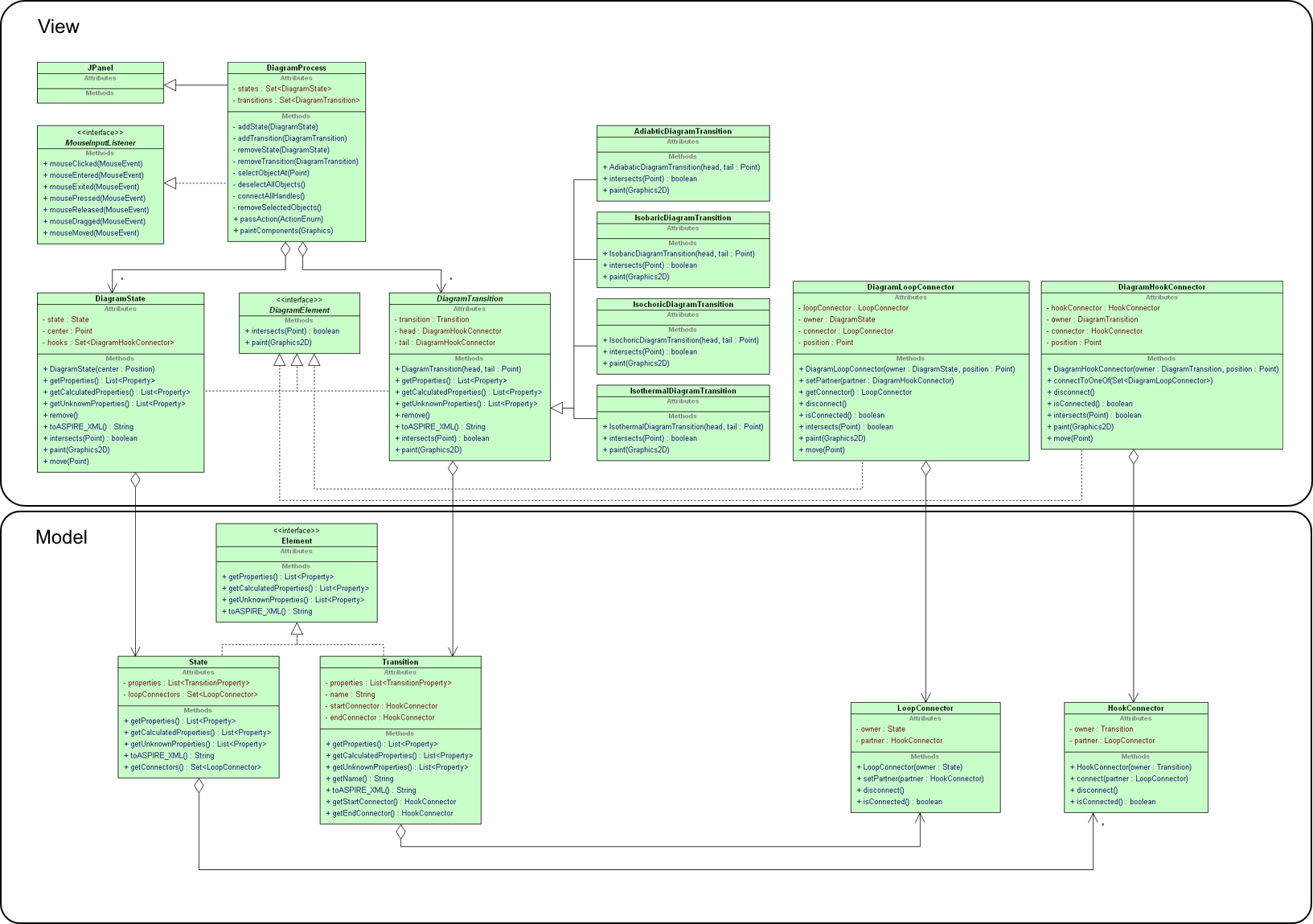
The following diagram shows the improved design for this part of the system. I will attempt to explain the design by firstly explaining the model, and then explaining how the view uses this model.
The Model: Some Notes
- There is no notion of positioning, nor painting. This functionality belongs to the view.
- There is no Process class. This is because the way these classes in the model are used is so heavily dependent on the view. All a Process class would be able to do is store Lists of States and Transitions, but the DiagramProcess class would still have to store Lists of DiagramStates and DiagramTransitions; so these collections would be redundant. In the spirit of eliminating redundancy I left it out, so it is up to the view to choose how to manage these classes.
- Instead of Handles, the design now uses LoopConnector and HookConnector. Transitions can only be joined to States and vice versa. This is an attempt to make the semantics of this more obvious. They are called Loops and Hooks to make the order of importance more obvious (I hope); you put a hook on a loop, not the other way around. I'm not entirely happy with this solution, but I struck the problem of where to put functionality when two classes are equally responsible for it. I chose to make one class primarily responsible. This means the HookConnector is primarily responsible for connecting and disconnecting from LoopConnectors.
- It makes more sense to imagine connecting Transitions to States than the other way around because of the nature of these two concepts. States are points of equilibrium which are defined in terms of absolute properties. Transitions represents the change between two states which is defined in terms of how properties change during that transition. What I'm trying to say is that states are usually more well defined and fixed on the diagram. They are also usually placed on the diagram first.
The Model: How Things Work
The model is concerned with how States and Transitions are connected and disconnected. It does not actually deal with creating or removing Elements from the diagram because the diagram doesn't exist at the model level.
- Connecting a Transition to a State: Tell the HookConnector to join to the LoopConnector by calling HookConnector.connect(LoopConnector). This sets HookConnector.partner directly, and sets LoopConnector.partner by calling LoopConnector.setPartner()
- Disconnecting Connectors: Call either LoopConnector.disconnect() or HookConnector.disconnect(). LoopConnector.disconnect() calls partner.disconnect() to do the real work. HookConnector.disconnect() nullifies HookConnector.partner directly and LoopConnector.partner via LoopConnector.setPartner()
The View: Some Notes
- There are classes to wrap each of the classes in the model. These classes should only be concerned with issues of the view. This basically means issues related to positioning and displaying. The relationships between instances of these classes should be captured by the model.
- The DiagramElement interface specifies that things on the diagram should be able to do two things; draw themselves, and tell you whether they intersect a specified Point. Unfortunately DiagramStates and DiagramTransitions must be handled separately, so this interface is probably of little use other than documenting what they must be capable of.
- The specified types of Transition class have been moved up to the view. The only differences between these Transitions is their shape; some are curved. So they will be displayed differently and intersect different points.
- The DiagramProcess represents the cycle as a whole and also handles all matters of user interaction (described in more detail later). I tried to represent the overall cycle in the model because this is where it semantically belongs. However, this ended up being redundant because the view must keep track of all its DiagramElements anyway.
- The DiagramProcess.setMode() method allows this class to be informed of external actions such as buttons on the toolbar being clicked. This allows the DiagramProcess to be entirely responsible for adding and repositioning elements on the diagram for Behavioral completeness. Unfortunately this may result in a Switch statement smell in this class. These ModeEnums haven't actually been shown on the diagram. They are fairly obvious; this is one for each action that doesn't occur immediately after pressing a button in the toolbar. Currently this is only adding states and transitions.
The View: How Things Work
- Adding a State:
- The user clicks the "Add State" button which calls DiagramProcess.setMode() which sets DiagramProcess.currentMode to the "add state mode"
- The next place the user clicks on the diagram will cause a DiagramState to be created and positioned there.
- The DiagramState is responsible for creating and positioning its DiagramLoopConnectors
- Adding a Transition:
- The user clicks one of the "Add Transition" buttons which calls DiagramProcess.setMode() which sets DiagramProcess.currentMode to the mode for the appropriate transition type (say "add adiabatic transition" for example).
- Clicking on the diagram is ignored
- The user must drag between two points on the diagram to place the Transition
- Connecting Objects:
- DiagramProcess calls its own connectAllHandles() method at appropriate times, say when a new Transition is added or a State is added or moved.
- connectAllHandles() gets all disconnected DiagramLoopConnectors and DiagramHookConnectors
- For each DiagramHookConnector it tells it to connect to one of the DiagramLoopConnectors if possible by calling DiagramHookConnector.connectToOneOf()
- Connecting is performed by calling HookConnector.connect() in the model.
- Removing Objects:
- The user clicks on the diagram. DiagramProcess selects the object at that position.
- The user clicks the "delete" button. This causes DiagramProcess.removeSelectedObjects() to be called.
- For each selected object:
- Firstly, call remove() on the DiagramState or DiagramTransition object
- This calls disconnect() on each DiagramLoopConnector or DiagramHookConnector. These methods simply call their respective disconnect() methods in the model.
- Remove that object from the List maintained by DiagramProcess
- Moving States:
- The user clicks and drags on the diagram. These events are all caught by DiagramProcess and so can be handled internally.
- Currently only DiagramStates can be moved. If the drag started on a DiagramState, then DiagramProcess tells the DiagramState to move to the Point where the drag ended by calling DiagramState.move()
- DiagramState.move() sets it's own position defined by DiagramState.center and calls move() on each of it's DiagramLoopConnectors
- DiagramLoopConnector.move() changes it's own position and calls DiagramHookConnector.move() on its partner.
- DiagramHookConnector.move() simple changes it's position.
- DiagramProcess.paintComponents() is called which repaints the whole diagram.
- This scheme works because of the way DiagramElements paint themselves. DiagramElements don't store their shapes (either circles or lines), they just create them from their other properties when their paint() method is called. This eliminates redundancy which simplifies the process of moving them.
Design Conflicts
Here I will summarise the things about this design that still keep me up at night. I will also try to explain the forces that eventually pulled me in the direction I went, and the consequences of this decision.
- My design for the Formulas and Equation section is possibly overly simple. I favoured simplicity over completeness. A more complete solution would be to implement a parser which creates a parse tree to represent a Formula. However, the advantages that this design would provide are currently not needed. A parse tree would make it much easier to perform more complex operations such as checking the Formula is valid, or evaluating the Expression to get a result. These sorts of operations are currently not necessary. This decision will mean that if more complex operations are to be supported, changes to the model will be needed. These changes will be fairly complex, and require changes to other parts of the system such as the view. However, this scenario is unlikely given the purpose of this system.
- I had great difficulty separating the model and view cleanly. This is most clearly evident in two parts of the design:
- DiagramProcess actually handles several things which could be considered separate. It is a JPanel which displays the diagram, catches and handles all mouse events, and manages the overall Process. I would have liked to have the notion of a Process defined at the model level. This would allow the DiagramProcess to only concern itself with matters of the view. The Process class would store collections States and Transitions and provide functionality for adding, removing, joining and disconnecting these objects. However, even with this Process class the DiagramProcess class would still be required to manage DiagramStates and DiagramTransitions. This would add a great source of redundancy. I favoured eliminating redundancy over separation of concerns.
- I wanted to define all relationships between States, Transitions and their Connectors at the model level. This was simple until you consider the case of moving objects around on the diagram. So these classes need to be aware of one another in some manner at the view level because this is where movement occurs. So it is also necessary to define these relationships at the view level. The observer pattern could possibly be used to make these relationships as abstract as possible, but I considered this unnecessary. I favoured simplicity because to me these relationships are not so bad; they make sense in some semantic manner. It's just unfortunate that they have to be duplicated at the model and view levels.
- These decisions, or rather this failure to fully separate the model and view, means that there is now more functionality in the view. This reduces the benefit of separating model and view; in particular it will be more difficult to replace the view or add another to the system.
- I also completely neglected to consider how MVC could help solve these problems. I only had this epiphany last night! I have the feeling that MVC could be what I was looking for to provide clean separation between model and view. I favoured ignorance over looking for existing solutions ;).
Enhanced Extensiblity
The design allows the program to be more easily extended in the following ways:
- Extra Properties can be easily added to Transitions and States by simply including them in the constructor of these classes.
- Extra formulas can be more easily added because all you need to pass is the whole formula as a String and the set of variables present in that Formula.
- A different view could be more easily put on top of the model because the model and view are cleanly separated.
Future Work
There are a few things that I would still like to look at further.
- Reconsider the separation of model and view. It seems to me there there is too much in the view now. I wish that I could have put more into the model. In particular, the idea of an overall Process (collection of States and Transitions) should belong to the model. Currently the view is responsible for this. I wonder if the notion of positioning actually belongs to the model rather than the view. This argument is potentially valid because positioning is an inherent characteristic of a diagram, not just a product of how it is displayed. If we considered positioning the responsibility of the model, I think that the model and view would separate much more easily.
- Reconsider how objects are exported to XML. Currently things export themselves, and this has resulted in a large amount of duplicate code. I think that this could be simplified a number of ways. One simple way might be to ask each class for a set of key-value pairs, and handle the formatting to XML in a separate class. I think the XML format is sufficiently simple to allow this. The visitor pattern may also be useful for this.
- Reconsider how IDs are assigned. The way this happens is currently quite inconsistent. Some classes are told their ID via their setID() method, others set their ID themselves. All get their ID from the static method Process.getNextID(). I'm not sure that this is conceptually the responsibility of Process, it is just a convenient place to put this method. In fact the IDs are only relevant for exporting to XML, and the only requirement is that they are unique. So the assigning of IDs could be made the responsibility of the export mechanism. However it is done it should be consistent.
- Consider how observer could be used. The initial design made quite heavy use of the Observer pattern. I believe that some of this was poorly done, however I get the feeling that observer could still be used to improve the design, particularly with respect to States, Transitions and Connectors. It could also be used to improve the separation between model and view. However, in the spirit of keeping it simple I chose to not use it at first.
- Reconsider the SpecialValue class. This is basically just a data class. It should be responsible for as much of the work related to special values as possible.
Conclusion
I have described the design of the Java Applet behind Thermo-Tutor; an ITS for introductory thermodynamics. This Applet must be able to allow the student to easily specify answers to thermodynamic problems. This includes drawing diagrams and using formulas to calculate unknown properties. The requirements of this Applet are fairly complex, so good OO design is crucial. A number of people have been involved in the development of this Applet, and no formal design was ever documented, so the resulting design has become quite convoluted. I have described this design, pointed out a number of areas where it is lacking, and proposed ways that the design could be improved in these areas. A number of areas of the design remain unexplored, and the changes I have proposed are by no means complete. There are a number of conflicting forces which continue to plague the design. I have explained how the design I have proposed has improved comprehensibility and extensibility. I have also provided some final thoughts about how I suspect the design could be further improved. Unfortunately, I have completely failed to show how my design can be implemented in code (see below).
Code
Unfortunately, after doing all this design I have experienced what is most affectionately known as:
Because, you see, now that I have come up with a design that is so drastically different from the original, I am now left the task of re-writing a 7000 line Java applet. Good one! Probably a bad choice for a design study. So I have opted to instead focus on ensuring that I have described my design and put down my thoughts in full. I can only hope that Wal in his infinite wisdom will be sympathetic. Besides, it's a design assignment right? Sweet.
The code for the two versions of the code is provided below. Note that I only began to implement the first of my suggested design improvements (ie. basically nothing). So the final version only differs in this regard, and doesn't even compile. I would recommend ignoring it completely.
- Original Code: Media:thermodynamics-applet-control.zip
- Final Code: Media:thermodynamics-applet-control-final.zip
