Oliver Cardwell/Project
This project takes an existing software design and gives it a good Object Oriented (OO) overhaul. It is broken into two parts;
- The first part looks at the existing software design and what its trying to achieve.
- The second part it the OO redesign that tries to incorporate some important patterns and principles of good OO design.
Contents |
Introduction
What is my project all about? Well for my honours project I am looking at the performance of iterative inverse kinematic algorithms. Yes there are a few big words in that title so I will break it down and you will see that its not so bad.
My project focuses on the inverse kinematics of simple joint chains such as a robotic arm or the leg of an computer animated character. If we want to position the end of the robotic arm (end-effector) then we need to tell each joint in the arm to move to a particular angle. Once the robot arm has moved each of its joints to the required position the end-effector will (hopefully) be in the desired position. The hard part of this and coincidently that 'inverse' part of the title is finding out what angles you need at each joint so that the end-effector ends up at the correct location. Enter the CCD algorithm ...
The Cyclic Coordinate Descent (CCD) algorithm is an iterative algorithm that operates on a joint chain and works by converging the end-effector to the desired target location. The CCD algorithm is relativity simple to implement and this makes it very popular for use in the fields of robotics and computer animation and computer games.
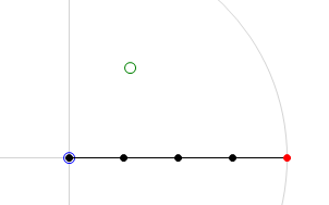
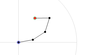
Below are two images that will help clarify what the CCD algorithm achieves. The first image is the 'before' shot. The joint chain is stretched out straight with the base of the joint chain at the origin. The green circle is the target location and the red circle is the end-effector of the joint chain. The second image is the 'after' shot. In this second image we can see the result of running the CCD algorithm on the joint chain. You will note that the end-effector has moved to the target location. This is a pretty good indication that everything has gone smoothly in the algorithm, it has been able to find the rotation required for each joint in order hit the target.
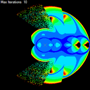
Ok so for each target we have a bunch of information regarding the behaviour of the CCD algorithm, these include the number of iterations done to get the end-effector to the target and others such as the total amount of rotation taken by all the joints. If we now use this information to colour the target and we make as many targets as there are pixels then we get a colourised map of performance of the algorithm with the joint chain. The result can be seen below.
Looks good, doesn't it. Now we can easily see how the CCD algorithm performs using a given set of parameters. We can see that it has trouble reaching around behind itself and we can clearly see the regions of the joint chains workspace that it can reach easily due the simple colouring. Ok now to get onto designing a nice simple object-oriented solution that will make generating various metric maps a snap. But first we need to look at some basic requirements.
Requirements
The program needs to able to render a metric map for a given size joint chain and a given iterative IK algorithm.
- Input
- Number of joints in the chain.
- Type of iterative IK algorithm (will be using at least two types initially but we want to be able to add more easily)
- Behaviour parameters for the algorithm, including:
- Maximum number of iterations to attempt
- Tolerance distance required for the end-effector to be considered at the target
- Size of the metric map (image dimensions size x size)
- Metric to display on the metric map
- Output
- Metric map (size x size) image
- Range of results for the rendered metric map
In order to render a metric map we follow the following general algorithm.
- Algorithm
- Create the required number of joints
- Create a 2D buffer to hold the results, one element for each pixel/target
- For each target in the buffer: (see note *)
- Reset the joint chain to its default position
- Run the algorithm over the joint chain for this target
- Save the result to the buffer
- Loop over the buffer and find the min and max (range) for the required metric
- Create an image the same size as the buffer
- For each element in the buffer:
- Use the resulting metric range to colourise the result
- Store the colour in the corresponding image pixel
* note: This loop can be very computationally expensive, especially with large images and high thresholds. So this loop is targeted for sub division to allow parallel execution.
Internally it does not really matter the structure or the representations as long as the CCD (or any alternative) algorithm works correctly and has access to the joint angles. In saying that lets check out the initial design.
Initial Design
The initial design follows closely to this simple step by step, procedural, approach to the problem of rendering a metric map. The steps are outlined as follows:
Description
First lets take a closer look at areas in the problem domain. These areas are not analogous to classes, but as we shall see, they are a close to the initial design.
- Structure
- First I identified what was going to be changing and the obvious answer is the joint chain. So I designed a Link (joint) class. This class would represent a single link with a static length and dynamic angle. Also included was a origin field that would be the 2D location of the base or origin of the joint.
- In order to represent a joint chain I would simply use an array of links. This way it naturally enforced an order and length, so therefore would work perfectly as a joint chain.
- Algorithm
- Next I needed a Solver that would take a joint chain and modify the angles of the joints until the end-effector was at a given target location. Knowing that I wanted to be able to test different algorithms, I made this class abstract and then implemented a concrete CCD class from it.
- Now that I had the ability to represent and solve a IK problem on a simple joint chain I needed a way to record what happened to the joint chain during the solve routine. So I created a Result class that kept the results of various metrics and made is the return value for the Solver.Solve() method. By doing this I let the implementation of the Solver take care about filling in the various metric values.
- Plot
- So far I think that I was off to a good start. I had simple classes to represent joint, solver and result. Now I need to take these and apply them to each pixel in an image and render the result using colours. Firstly I decided that I need to collect all the data. So next up I designed a Plotter class. This class would have the responsibility of creating a 2D array of results, each result representing a point in a square grid that would then be mapped onto a pixel in a square image (metric map). The plotter class turned out to only have a single method and did not need to contain any state between calls so this class was defined as a static class with a single static method. Through this method you could pass all the required information the plotter needed to produce a 2D array of results. I thought this was a nice solution as it kept all the behaviour of the solver in a single call and would allow me to break the problem up further into chunks that I could process simultaneously over multiple threads. So that's exactly what I did. (Note: PlotThreaded() and the internal Job class).
- Summarise
- Great now we only need to loop over all the results in the results buffer (2D array) and compute a colour value for each result, saving the computed colour to a cosponsoring image pixel. But how do I know what metric we want to show and what is the range of that metric in our result buffer? An into the fray I designed the Statistics class. This class would simply loop through the results buffer and compile a series of ranges for each metric in the result class. In this case I decided that I did not want it doing all that work in the constructor so I made the default constructor private and instead created a static method that when called would create and return the class with all the field filled in. In this way only the static method creates the and has write access to the classes field. What's returned is effectively a 'read-only' class.
- Render
- For the final step I needed a way to colourise each result. Because the bulk of this operation would be the same no matter what metric we wanted to measure I decided to design a Renderer class. This would do all the grunt work of looping over results and then I would use a simple delegate method Colourise, passed to the renderer, do the simple job of selecting the appropriate metric and using the metrics range define a colour value.
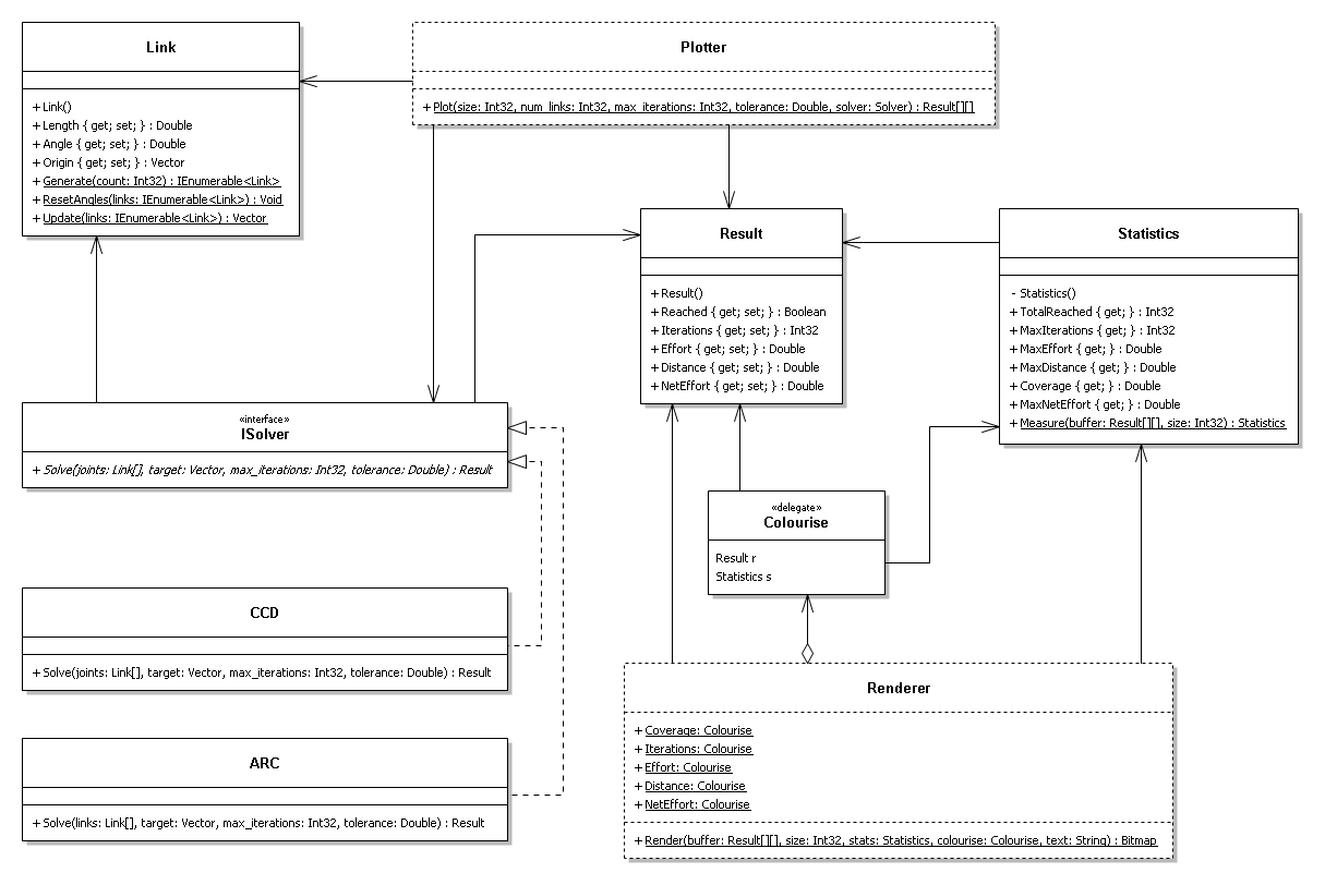
UML Diagram
Class Descriptions
- Link Class
- The Link class is farily straigt forward. It simply represents a structure with a length and angle value. It also contains an origin vector that represents the location of the base of the link in the chain.
- ISolver Interface
- The abstract solver class is a template for a solve behaviour, or solve algorithm. The solver class outlines a single Solve() method that takes a number of parameters including a list of links and returns a result.
- CCD Class
- The CCD class implements from the Isolver interface, and implements the CCD algorithm through the Solve() method.
- ARC Class
- Like the CCD class, the ARC class implements from the Isolver interface, and implements an experimental IK algorithm through the Solve() method.
- Result Class
- The result class is a simple data class. It contains the resulting metrics from a call to a Solve() method from the abstract solver class.
- Plotter Class (static)
- The static plotter class has only a single method, Plot() and no state. This single method take a number of parameters for generating a result for each point on a square grid and does just that. The Plot() method returns a 2D array of results, one for each point on the square grid. This approach therefore computes all possible metrics in a single pass.
- Statistics Class
- The statistics class is a simple read-only summary of results class. The class is given a list of results through its static method Measure(), and produces a summary of all the results. These include finding the maximum values and tallies.
- Colourise (delegate)
- The colourise delegate, simply templates a method that takes a result and the summary of results and returns an appropriate colour for a certain metric. Therefore in order to produce different metric maps of different metrics, or colour scales, we simply have to write a method with the same signature and pass it to the Render() method on the static renderer class.
- Renderer Class (static)
- The static renderer class, like the static plotter class, has a single method and no state. The Render() method takes a number of parameters including a 2D array of results, one per pixel, and a colourise delegate (behaviour). It uses the colourise delegate to create a coloured image of the results.
Discussion
Ok now we have finished the initial design we can put on our OO hat and take a closer look.
The first thing we may notice is that there is not a lot of OO going on here. Sure we have used classes to implement a "separation of concerns" but a lot of those classes appear to have no state. Should this be a concern? What's with all the static methods in Link? And what's with the private constructor in the Statistics class? Why are we passing around a list of links everywhere? And why are we passing the size of the 2D results array with the results? A lot of stuff in this current design does not make nice OO reading.
We will try and address all these in the OO redesign.
OO Redesign
Given the initial design, it is obvious that we need to give it a thorough OO makeover. So here we go...
Description
For starters lets look more closely at the problem domain and see if we cannot separate the current procedural based design into recognisable and useful objects.
- Structure and IK Behaviour
- The concept of a Link has a strong relation to the real world, and great for encapsulating in OO so we will leave that class mostly intact. We will however remove the Origin property from the class. This property is the direct result of the links parents and their length and angle properties. We will move this concern somewhere else. Now looking at the initial design we seem to be passing a list of Links around quite a bit. We also seem to be doing operations on these Links lists in other various classes, inside the Link class itself. This is a great candidate for encapsulation into a object that represent a list of Links. So we will do just that and create a Chain class. This Chain class will represent a list of Links and concern itself only with making manipulating and maintaining the Links. The Chain class will hold the Origins for each Link as they are not needed to any other classes and we can call the Update() method on a chain class to find the location of the Chain's end-effector.
- Building on this idea of a Chain class we can now add a move behaviour. This move behaviour will be the CCD algorithm, or any other IK algorithm that we would like to implement. The simplest way to achieve this in OO style is to make the chain class an abstract class and template and abstract Move() method. This Move() method will be passed a target and will return the result of the move. In this way we can create and use a new IK algorithm by simply inheriting from the abstract chain class and implementing its own Move() method.
Already we have tidied up a large portion of the initial design and brought it more in-line with OO practice and principles. We have have limited the use of the link class to the abstract Chain class. This reduces coupling and allows for a more abstract approach to the design. The Chain class allows the links to be manipulated by an inheriting class giving you a large amount of flexibility when implementing and trialling a new IK algorithm.
- Generating Metric Maps
- Now lets look at the generation of a metric map. If we are to describe what a metric map is in the form of an object, it is the a simple grid of target points that cover the workspace of a link chain. Ok excellent, we just hit the OO nail on the head, and even got the name for the new class, we will call this a Workspace class. We can create a Workspace class that is a grid of targets. These targets are what the chain will try and move to, each time producing a result. So if we create a simple Target class that contains the coordinates of the target point and a Result object then we can have the Workspace class take care of creating them and maintaining the grid. The behaviour that we want the workspace class to have is to take a chain, and get this chain to move to each of the target points in turn, storing the result. This structure also makes it easy to extend to a multi-threaded environment, as we can divide up the targets (jobs) among many Chains (workers) and have them all operate in parallel.
- Despite the Result class from the initial design having a "Data class smell" it is somewhat unavoidable in this design. We need to store the results somehow and all the result are simple boolean or number values. Therefore we will use this class again in the OO redesign.
We are going to move away from the idea of a statistics class in the OO redesign, for a couple of reasons. The main reason being that when we colour a metric map we don't necessarily want the colour scale normalised. For example a normalised colour scale does not allow for an easy comparison between different metric maps, as each map will be normalised independently. Instead we will look to have the colour range flexible and therefore allow us to create metric maps that we can visually compare.
- Colouring Metric Maps
- This area of the redesign needs to change quite a bit from the initial design. We can look at a metric map as the coloured representation of the workspace of a chain. That's great we can use that as the base class. So we will define an abstract MetricMap class. This class will have a Generate() method that will loop over each result in a workspace and then produce a colour for each point, finally returning a coloured image. The MetricMap class will template a Colourise() method that will be responsible for converting a result object into a colour.
- This will work well for simple metrics, like the coverage metric. This metric will produce and image that is black where the chain failed to reach and white where it did. So if we inherit directly from the MetricMap class we can implement the Colourise() method to check for coverage and return either black or white.
- However this is not so simple for other number based metrics. To accomodate these we will further abstract and extend the MetricMap class to allow a range (min..max) to be specified. We also need the new abstraction to be able to handle different number types, ie int or double etc. So to achieve this we create an abstract RangedMetricMap<T> class and make it generic. This RangedMetricMap<T> class inherits from the MetricMap class and allows a number type and range to be given. So when we need to create a metric map of the number of iterations taken to reach each point, and have them coloured in the range of 0..max_iterations we can inherit from the RangedMetricMap<T> with a type of int. Then in the implementation of the Colourise() method we have type same access to a data range to compare the metric too.
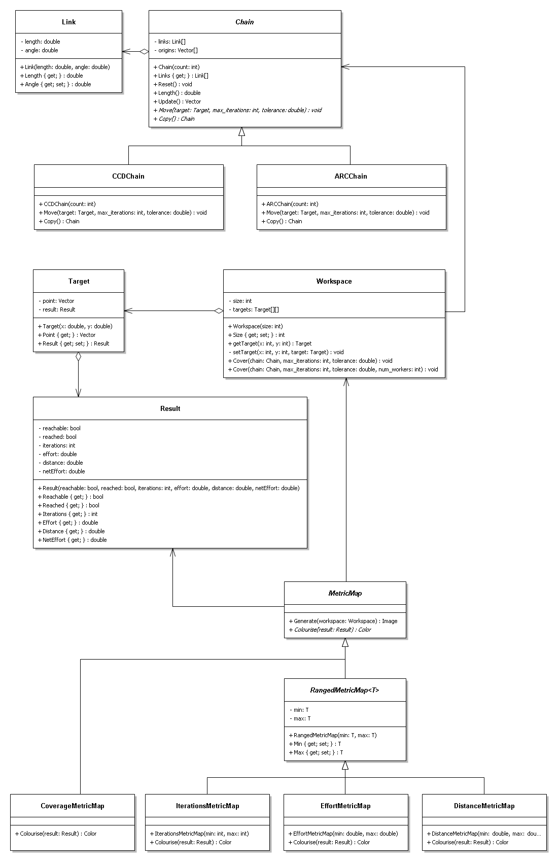
Ok so we have made quite a few changes to the initial design. We have given it a good OO makeover, so lets now take a look at the UML diagram of the redesign.
UML Diagram
Class Descriptions
- Link Class
- This falls straight out of the problem domain. It simply has a static length and a offset current angle.
- Chain Class (abstract)
- Again this comes straight out of the problem domain. A chain is simply a list of links. By looking at the chain as its own object we can use it as the basis for a couple of routines that we do on a chain, such as get the chain's length or reset the angle on each link in the chain. Most importantly though, we can allow an inheriting class implement the behaviour of the Move() method. This method is where the IK algorithm happens in the sub-class.
- CCDChain Class
- This is the infamous CCD algorithm. This class inherits from the abstract Chain class and implements the Move() method in accordance with CCD algorithm.
- ARCChain Class
- This is the ARC algorithm, an experimental IK algorithm. Like the CCDChain, this class inherits from the abstract Chain class and implements the ARC behaviour through Move() method.
- Result Class
- This class is a simple read-only data class. It is generated by the chain's Move() method. An object of type Chain must fill in all the parameters of the Result class through the Result class's constructor. Once the Result class is constructed, all the values are read-only. This is because we do not want the Result classes values to be tampered with by another object.
- Target Class
- This class represents the instructions and results of a chain moving it's end-effector to a target. The Target class groups together a target point (x,y), and the Result object. The target point is generated by the Workspace class and the Result class is generated by the Move() method in the Chain class.
- Workspace Class
- This is the workspace of a chain. Essentially it is a collection of Target objects that the chain will try and move to. Each of these targets corresponds to a pixel in the final metric map but for now they hold the the target point and the result of the chain's move, ready to be transformed into a coloured metric map. The Workspace class takes care of generating the results to all the targets from the given chain, through the Cover() method. To speed up this potentially expensive operation an optional third argument can be passed to the Cover() method that uses a thread-pool to share the computational load.
- MetricMap Class (abstract)
- This class is the base class for any type of metric map. It takes care of creating an image and loops over a workspace given to the Generate() method mapping a colour to each pixel through its abstract Colourise() method.
- RangedMetricMap<T> Class (abstract)
- This class extends a MetricMap class by allow you specify a type <T> and a range (min, max) that the metric will be compared to for colouring.
- CoverageMetricMap Class
- This simple class implements MetricMap class. Because it will only be displaying a colour if the target was reached we do not need to inherit from the RangedMetricMap<T> class. Instead we simply implement the Colourise() method to return black, if the target was not reached, and white if it was.
- IterationsMetricMap Class
- This time we inherit from the RangedMetricMap<T> and use a type of int. Therefore we can construct this metricmap with a min and max parameter and have the colour scaled between these values. This is an important property because it allows use to use the same range between different chain configurations and therefore get a better comparison between them.
- EffortMetricMap Class
- Again we inherit from the RangedMetricMap<T> class, this time with type of double. This class shows the amount of effort taken to reach each target point.
- DistanceMetricMap Class
- Again we inherit from the RangedMetricMap<T> class, this time with type of double. This class shows the distance travelled by the end-effector to reach each target point.
Discussion
We are now in a position to compare the initial design and the revamped OO design. We have gone from a working flexible system to another working flexible system, so what have we gained my taking an OO approach to design?
In the initial design we were able to easily add new IK algorithms by implementing from the ISolver interface and implementing the Solve() method. In the OO redesign we are also able to easily add new IK algorithms by inheriting from the abstract Chain class and implementing the Move() method. What did we gain? Well by encapsulating the idea of a Chain, as a list of Links we were able to group together all procedures concerning a Chain into the single abstract class. And we simply leave the inheriting class to fill in the behaviour.
In the initial design we were able to easily add new image renderers by supplying the Render() method in the static Renderer class with a new Colourise delegate. In the OO redesign we are able to easily add new image renderers by inheriting from the abstract MetricMap or RangedMetricMap<T> classes and implementing the Colourise() method. What did we gain? Again by encapsulating the idea of a metric map into the abstract MetricMap class, we are able to write a generic Generate() method, thus allowing an inheriting class to implement the colourise behaviour. This follows closely the important OO "open closed principle". The basic generation of a metric map is wrapped up and therefore closed to modifcation, but buy exposing the Colourise() method is open for extension. An example of this is how we are able to introduce the abstract RangedMetricMap<T> class that extends the functionality of a MetricMap without having to modify the MetricMap class.
The biggest enhancement to the design is its simplicity. By capturing the essential elements of the problem domain into recognisable objects and operating on these object in an intuitive manner we are able to gain a clearer picture of what's going on and what objects are responsible for various states and behaviours.
Design Patterns Used
In a small project of this size we are unlikely to be swimming in design patterns, though there are a couple of very simple patterns that we used to tackle different problems. The following gives an overview of the patterns used in the redesign.
- Strategy Pattern
- The strategy pattern is used in the redesign to supply the Workspace class with a chain behaviour. By inheriting from the abstract Chain class and implementing the Move() method we are able to have a chain move using various IK algorithms.
- If we compare the redesign to the strategy model;
- The Chain class is the Strategy, with the Move() method being the AlgorithmInterface() method.
- The Workspace class is the Context, with the Cover() method being the ContextInterface() method.
- The CCDChain and ARCChain classes are the ConcreteStrategy classes, implementing the AlgorithmInterface() method.
- Prototype Pattern
- This pattern is not to obvious looking at the redesign UML diagram. Essentially we use the prototype pattern to duplicate a chain. When we run this model on multiple threads we break up the workspace into equal parts and then create duplicate chain to work on each part of the workspace. In order to create a deep copy of the chain we template a Copy() method on the abstract Chain class, thus enforcing any inheriting classes to implement a deep copy routine. This approach was needed because we need to essentially create a new instance of a chain and therefore, because the base Chain class is abstract we cannot create a new instance. Instead we must delegate that responsibility to inheriting subclasses.
- If we compare the redesign to the prototype model;
- The Workspace class is the Client, that calls a chains Copy() method.
- The abstract Chain class is the Prototype.
- The CCDChain and ARCChain classes are the ConcretePrototypes.
Design Principles Used
The redesign contains many example of OO design principles, some obvious and on purpose others not so much. There are also a number of design principles violated. I will touch on a few of these now.
- The Single Responsibility Principle (SRP): All of the classes in the redesign were created with this principle in mind. For example, the Chain class had only one responsibility, to manage the list of links. The Workspace class had only one responsibility, to manage the metric grid.
- Open Closed Principle (OCP): An example of this principle at work in the redesign is mentioned in the Discussion section above.
- Dependency Inversion Principle (DIP): In all cases in the resign we use the base (abstract) classes. We never need to call a concrete class directly where it inherits from an abstract base class.
Conclusion
Although it could be argued that we have not gained a lot from redesigning this to a more OO based design, I believe that we have come along way to simplifying and clarifying the approach. Although not startlingly obvious in a project of this size, managing complexity in an efficient way pays of big time in much larger project.
We have shown how the use of a few design patterns and sticking to some simple but important OO design principles can help in designing flexible and maintainable software, even on this small scale.
Files
Source A copy of the source project can be found here. You will need at leastVisual Studio 2008 and the .Net 3.5 runtime.
Installation
- Download and extract
- Open the solution file with Visual Studio
- Compile and run in the standard way
Comments
Please leave any comments that you have regarding this project or even the writing of this wiki page in this comments section.
Made a few grammar changes and added links. LukeRobinson
- Thanks Mr Robinson, I see now that my UML diagram is missing almost all of its associations. Fixed now.
