Tanmay's Design Study
Contents |
Introduction
Welcome to the world of Digital Logic. Ever wondered what they teach at the College of Engineering that is different from the material taught at Department of Computer Science and Software Engineering ? Being a computer engineering student, I took this opportunity to perform an Object-Oriented Analysis and Design of a 'Digital Logic Circuit Simulator'. Digital Circuits are constructed by joining simple logic elements and form the basis of our 'Embedded Systems' oriented programme. The system was designed and implemented specially for COSC427, and was not a part of another university project.
Background
Building complex digital structures like computers and microcontrollers without a simulation tool is similar to releasing a program without compiling/testing. Hence, designers always resort to simulation tools to check the correctness of their design before building the prototype. These circuits are essentially complex networks of simple logic components like logic gates, wires, clocks etc.
Logic Gates
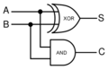
Half Adder Circuit
Full Adder Block Diagram
Full Adder Symbol


A digital logic simulator gives the user an ability to join simple logic elements in order to study the behaviour of complex digital circuits. My approach to this problem was to design an 'Event Driven Simulator' where events (change in state of something) trigger further events in the system at a later time. The main tasks revolved around the elementary components of the circuit and scheduling events that take place in the system. These can be further broken down into :
- 1) Wires --- These carry digital logic signals between components and have state associated with them.
- 2) Digital Function Blocks --- These perform functions to generate output signal(s) based on input signal changes. They need to listen for changes in the state of wires connected to the inputs of these blocks. An example of a function block is an and logic gate. It performs the bitwise AND function ( X = A.B) over inputs A and B.
- 3) Events --- The simulation is purely event based. This means that changes in the state of a wire can lead to generation of various events in the system. These contain a timestamp of execution along with the associated component.
My primary focus for this design study was on modelling the core classes of the simulator rather than its GUI implementation. The aim was to design a system that modelled the real world and could be extended in the future to incorporate GUIs and more components/ modelling techniques.
Requirements
- 1) Adding components : A User should be able to add new components to the system. These components can be a basic logic element or a combination of a series of elements. The user should also be able to copy simple elements in order to quickly build up a circuit. This is useful as many basic elements like logic gates are repeated in the circuit.
- 2) Connecting components with wires : A user should be able to assign connecting wires to the component input/ output ports. On connection, the component should be ready to respond to changes in the state of the wire.
- 3) Scheduling events: Timing is crucial in a digital logic simulation. This makes scheduling events an important task for this 'event driven' simulation software. Function blocks generate events with variable time delays (also known as propagation delays). These need to be executed by the system in the correct order, else the final output of the simulation would be incorrect.
- 3) Running the simulation and viewing results : Once the circuit has been wired up, a user should be able to run the simulation and view the results of the simulation. At this point, a basic text based output with timing information was sufficient. However, a GUI output (showing a graph) might be desired in the future.
UML Diagram Of Design

Design Detail
The focus was to make the design simple and extensible. Most of the classes map to the requirements discussed in the previous section. The design models the real world, as most of the classes were designed keeping in mind the circuits people work with and the things they need to simulate.
- Component and Port: The component represents a functional block in the circuit. Every component has at least one port to interact with the rest of the circuit. Ports could be input ports or output ports. Components could be in the form of simple logic gates (and/or/xor/nand) or a combination of these forming more complex components (like adders). To represent this part-whole heirarchy of components, the Composite pattern was used in the design. Logical circuits usually involve a huge number of the same components (like and/or gates). Prototype pattern was used To help the user quickly build up the circuit. This allows the user to create just one ComponentModule object and use the copy() method to generate multiple objects of the same kind.
- Wire : As described above, a wire is a container for a logic signal and links the output of one component to the input of another. As the signal propagates along the circuit, various events are generated to update the state of the wire after a certain delay interval. The user assigns a name to the wire on creation which can be used for generating the simulation results. The observer pattern was used to assist the wire in informing the connected ports about the change in its state. Input Ports add themselves as observers to the wire. This also allows us to model T-Junctions in the circuit (same wire going into multiple ports ) without having to add Junction type components each time. A wire class was designed instead of the
- Event: The Event class represents a discrete logic event that occurs in the simulation. A generic event has a time stamp and a task to execute at that time in the simulation. At the moment, events are created when a component changes the value of its output(s) based on the change in state of its input(s). The Event has a fire() method, which allows the system to execute it when required.
- Logic Level: This is a simple enumeration to model the IEEE Logic Levels. It offered a better abstraction to Logic High and Logic Low rather than using boolean variables for the representation. It would also allow addition of 'z' or high impedance signal level if required, without breaking the current design.
- Simulator: Performs the function of simulating the digital circuit by firing timely events. It contains a priority queue to which events are added and arranged based on the first one to be executed.
Design Patterns
Design patterns were used in this design to model the domain and solve challenging design problems. The design patterns used have been listed below, along with an explanation of how they were applied.
Observer
The model implements the observer pattern in two different areas in the design . It uses Observer pattern to model the relationship between wires (subjects) and components(observables). Change in the state of a wire demands re-computation of the outputs of attached ports, which triggers events in the system. The observer helps in automatically updating all the dependents in the one-to-many relationship modelled in the design. A port is added to the list of observers of the wire as soon as it is wired up. This helps us in modelling the real world, where on soldering a wire to a component, we expect it to change with changes to the state of the wire.
Another place the observer pattern was found to be applicable for the software and its future extensions was in the Simulator Class. The simulator is the observable in this case, which contains the event queue. The Observers could be in the form of different User Interfaces/ Event Loggers. These would be updated on execution of the event, and would react differently to the information. For example, A SimpleSimulatorApp would just display the event timing and information on the console/ text file whereas a SimulationGUIApp could use it to update the simulation window. This can help with easily adding various interfaces that can take the simulator to the next level.
Command
The Event-driven simulator that was designed in the project revolved around modelling discrete-time events that take place in the system. Even though change in logic levels were the main events that were implemented in the current version of the code, this pattern permits easy addition of different types of events in the future. The things common to all events, which include the timestamp and the fire() method were incorporated in the Abstract Event class. Other properties were left to be added by the subclasses. One such example is the WireLevelChangeEvent which involves change in the level of the wire at a specific time in the simulation.
In this case:
- Command Abstract Class : Event
- Concrete Command: WireLevelChangeEvent
- execute() Method: fire()
- Receiver: Wire
- action() Method: setLogicLevel(LogicLevel newLogicLevel)
Composite
The composite design pattern was used to structure the part whole heirarchy of the digital logic components or function blocks. Complex circuit function blocks are often made up of a number of smaller components. It would allow the user to easily build complex logic structures using this hierarchy. A simple example of such a representation is a HalfAdder which is made up of simple logic gates. It allows clients to treat individual objects and compositions of objects uniformly. The pattern is applied to the design as follows:
- Component Interface : Component ( real world name !! )
- Leaf: BasicComponent and subclasses like AndGate, XorGate etc..
- Composite: ComponentModule. (A module is a general term used for a logic block of components supplied by a manufacturer as a bundle which can be directly plugged into the circuits, for example a Wi-Fi module).
Prototype
Circuit designers want to translate their paper designs quickly to the computer, simulate and check the results. The prototype pattern was used in the design for this reason. It gives the user the power to create new objects by copying previous ones. Hence, a designer can create multiple components of the same kind by simply calling the copy() method on the components.
Singleton
The (controversial!) singleton design pattern was used to model the Simulator class. In the real world, you only have a single simulator working on the circuit at a given time. Using multiple simulators in neither possible nor beneficial in an event driven simulation, where the result is dependent on the timing of the simulation and execution of discrete events. Hence in this case the Singleton allows the user to create a class that is itself responsible for making sure no one ever calls the constructor (which could corrupt the simulation execution and results). The getSimulator() static method allows components to post events to the system simulator. The alternative could have been to pass an instance of the simulator to each and every Component which was ever being created, but that would mean unnecessary duplication of code and added complexity. Hence the use of the singleton pattern can be justified in this case.
Maxims and Heuristics
Various design heuristics learnt during COSC427 were used for evaluating and justifying design decisions when in doubt. Some of the heuristics followed include:
Tell, don't ask and Related Maxims
I feel this heuristic defines the spirit of Object Oriented Programming and helps reduce coupling between objects. In the design, I tried to follow the rule that objects don't ask for information from other objects and then act on it. Instead, they tell other objects to do the work by giving the necessary information. The design follows this principle at a number of places. A good example was through the use of the command design pattern, where the receiver (Simulator) simply calls the fire() method on the Event objects. It involves telling them to perform their operations without asking them for any information and doing the work itself. It also helps eliminate the Switch statement smell which would have resulted if the simulator would be checking the 'Class Type' of the objects for each event it received instead. It also encourages programming to the interface, not the implementation. The Simulator only needs to know about the Event interface and not the concrete implementation to run the simulation.
Open closed principle
The open closed principle has been followed at various points in the design. The world of digital logic is highly dynamic, where new components can keep entering the market with different properties, different port structure and different functionality. The code allows various subtypes to be added to the Composite hierarchy of components. It also allows complex components to be created from various basic components adding more flexibility to the design. Another place where OCP was followed was in the Event Interface. Different events can be modelled by the simulator in the future by implementing the Event interface. The high level composite hierarchy was developed as abstract as possible.
Model the real world
A simulation models the real world in itself, by allowing designers to perform the real world tasks in software. I decided to use the same technique during this design which lead to a model that is intuitive for the user/ maintainer. This lead to the birth of Components and Modules (with Ports) and wires that carry signals.
Discussion and Design Critique
Design patterns solve complex problems but also break rules by trading off non-critical functionality or flaws with important requirements of the design. This section explains the forces which were balanced with the help of the design patterns and the various trade-offs or flaws introduced in the design as a result of this.
- No-op overrides vs. Dependency inversion principle: This is a known problem with the composite design pattern, where allowing the client to treat individual elements and compositions with a similar interface can lead to leaf sub classes overriding super class methods with blank implementations. Using the alternative 'as-leaf()' methods leads to violating the dependency inversion principle. In this case, I was more tempted to follow the standard Composite pattern as the dependency inversion is not something that is followed completely by Digital Logic Modules in the real world. High Level modules do depend upon lower level modules for carrying signals internally, and hence the dependence cannot be classified as extremely evil in this case.
- Push vs. Pull Configurations for updates: The Observer pattern has been implemented in two different ways in literature. The 'Push' configuration focuses on passing the related data along with the update method (as parameters), while other just notifies the observers about a change in the state. It then expects them to collect the information via getState() methods of the Subject Class and act on it. I preferred the Push Configuration as wires only carry a LogicLevel signal which they need to pass to the listening ports. This also obeyed Tell, don't ask principle and reduced the coupling between the wire and port.
- God class: As stated earlier, the technique of modelling the real world was used during the design process. Even though most of the classes were designed based on this principle, the Simulator Class somewhat breaks this rule as it performs multiple tasks of running the simulation and also acting as the scheduler. However, this was a choice between the single responsibility principle and keeping related data and behavior in one place. It was important for the simulator to contain the priority Queue of events if it had to act as the Observable, allowing multiple interfaces to be updated on execution of Simulation Events. Not doing so would have lead to a lot of interaction/ coupling between the divided Simulator, the Scheduler and Component Classes. Not going with a singleton pattern would have required passing the Simulator instance to each and every component. Hence, this acted as a near optimal solution for this design problem.